Designing for FDM: Best Practices from an Engineer
When most people think of 3D printing, they picture pushing a button and getting a perfect part. But if you’ve spent any time with an FDM printer, you know the reality is more nuanced. As a mechanical engineer who’s worked extensively with FDM printing—both professionally for prototyping and personally for causes like Toys for Tots—I’ve learned that great prints don’t just happen. They start with smart design.
Here are some best practices I use when designing for FDM:
1. Think Like the Printer
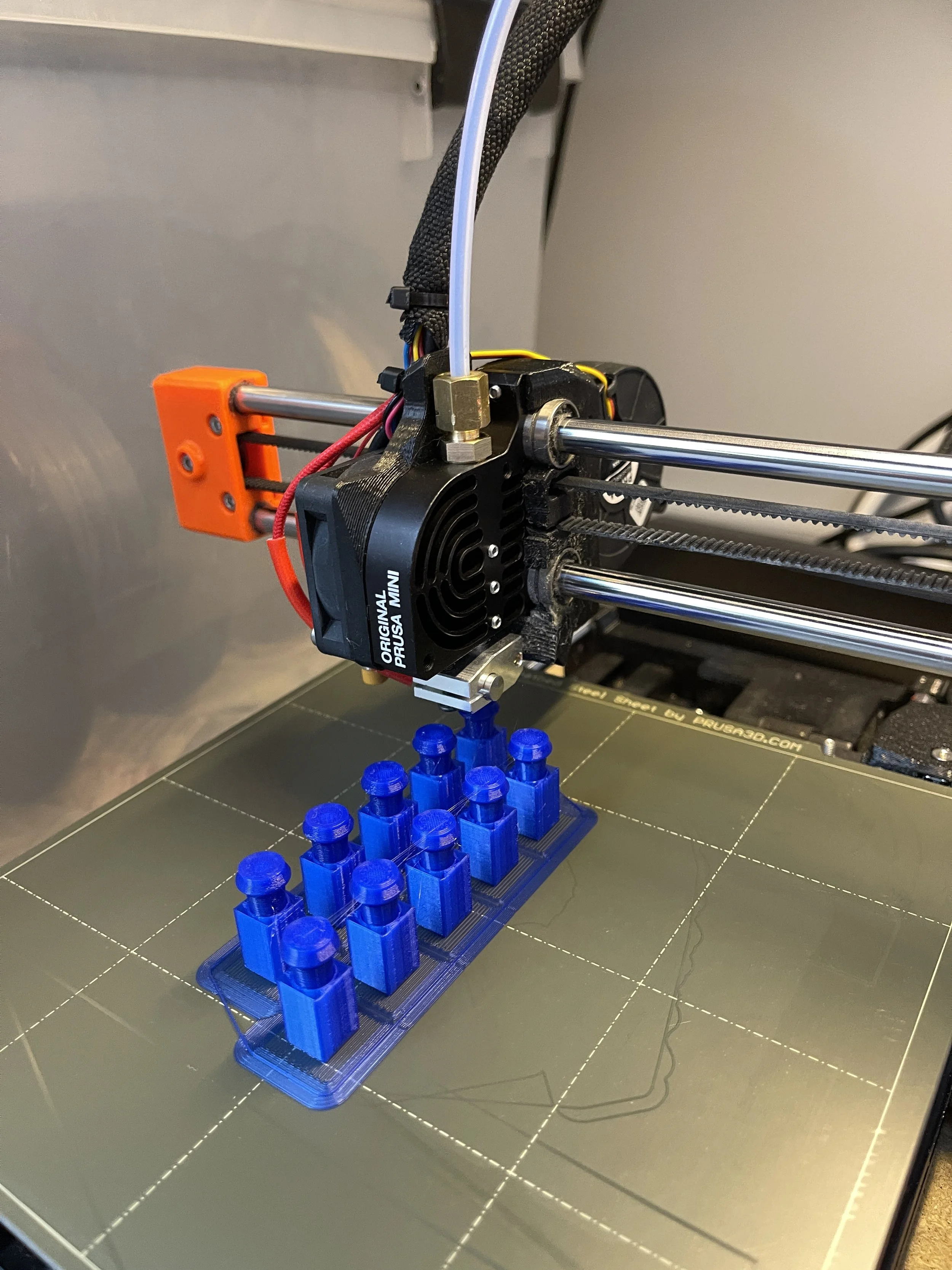
FDM printers build parts layer by layer, which means they have limitations based on orientation, overhangs, and support. If a feature is hanging out in space with nothing underneath it, the printer may struggle.
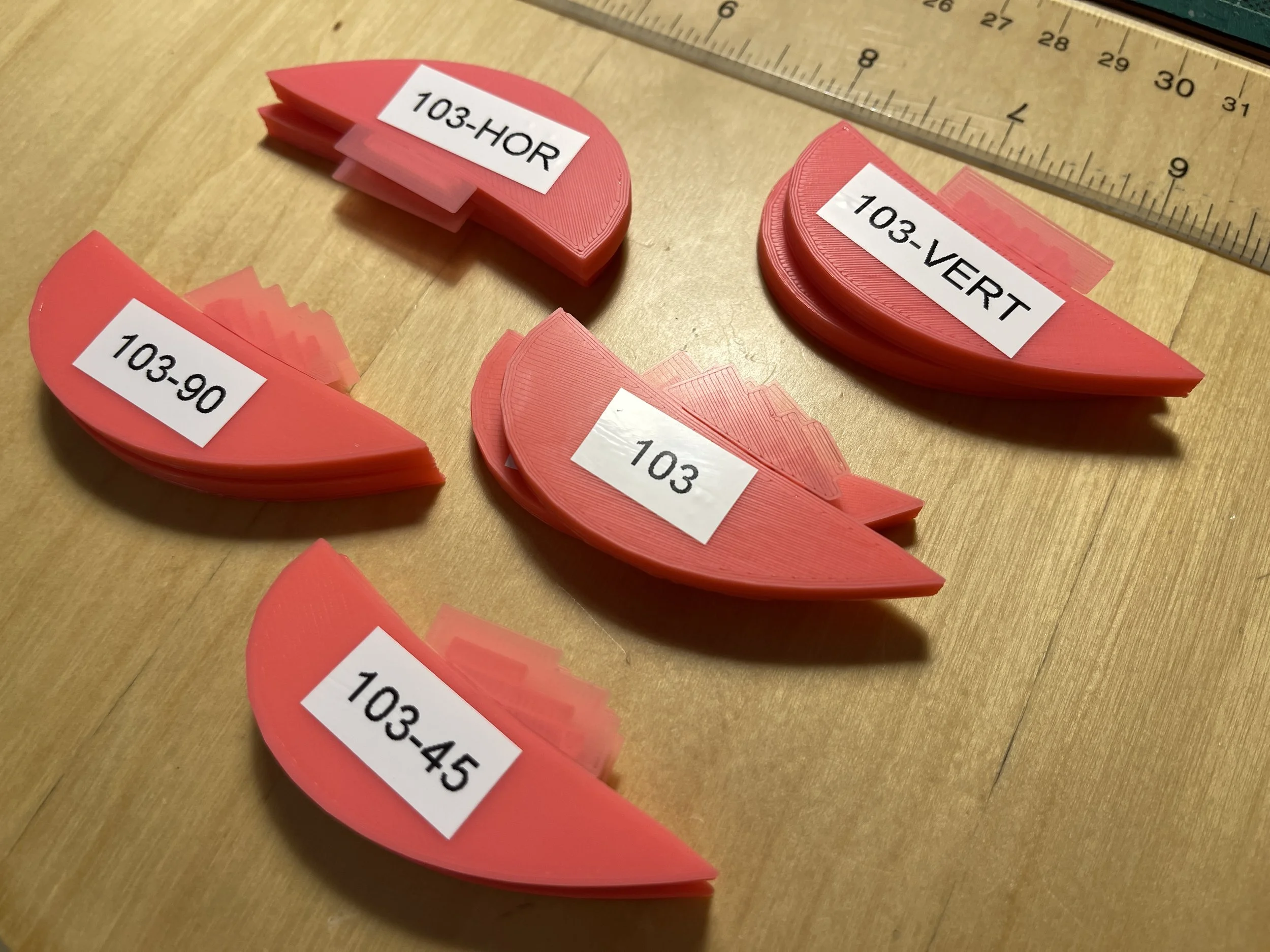
2. Consider Layer Adhesion and Strength Orientation
Parts printed in FDM are weakest between layers (along the Z-axis), so orientation matters. If you're designing a functional part that needs to bear load, think about where that load will go and orient the part so it's handled along the strongest axis.
You can as consider which material you use. PETG will have much better layer to layer adhesion than PLA but tends to cost more. But if you need mechanical strength PETG is the way to go.
3. Use Reasonable Tolerances
FDM printers aren't injection molding machines—they have limits. Too-tight tolerances can lead to fused parts or hours of post-processing, while too-loose ones create sloppy fits.
General guideline:
Press fit: 0.1–0.2 mm clearance
Slip fit: 0.3–0.5 mm clearance
Loose fit or clearance for screws: 0.5–0.7 mm
Of course, dialing in a very specific fit may require some iteration.
4. Design With Supports in Mind
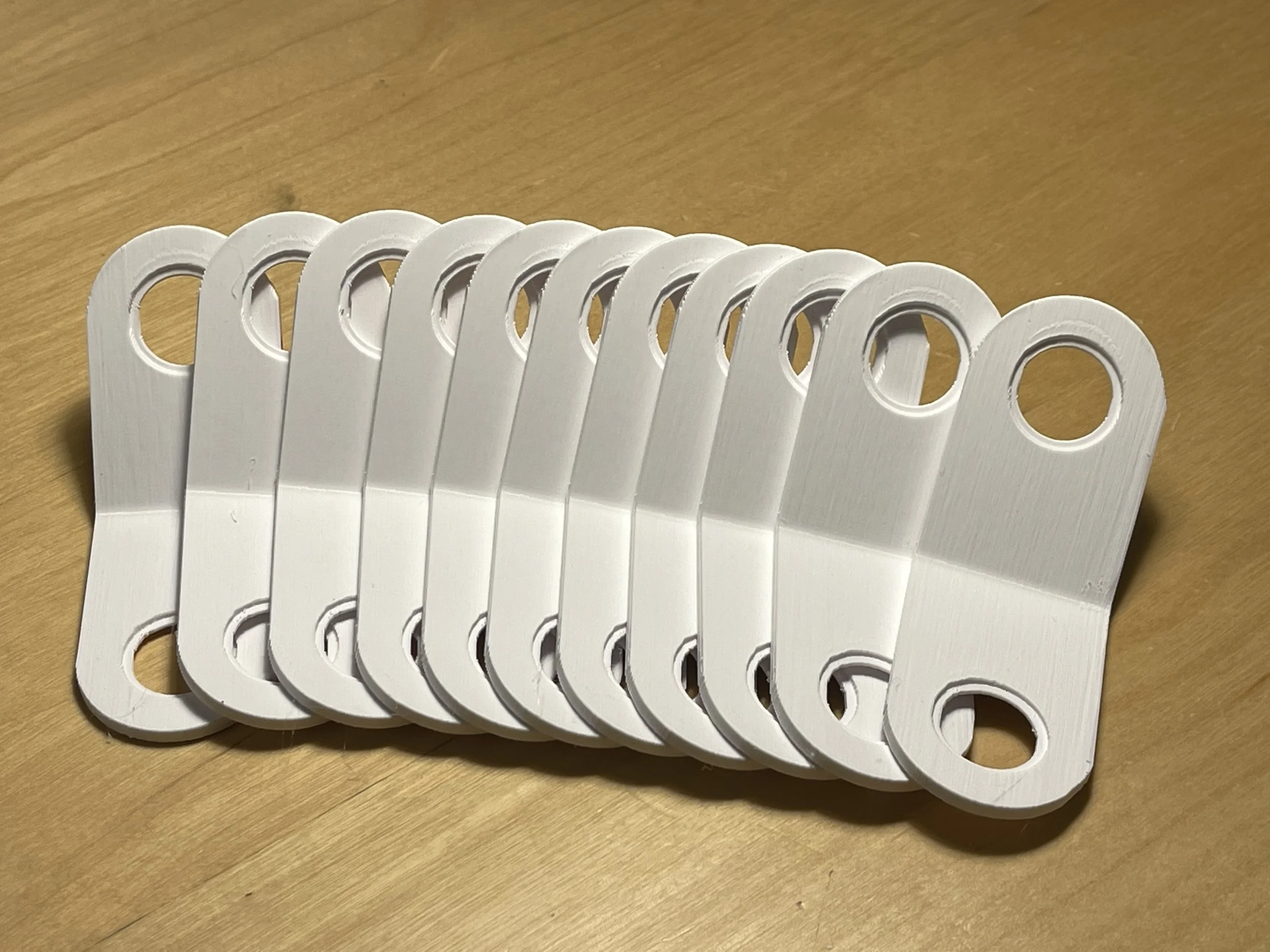
If your part needs supports, where will they go? Will they be easy to remove? Will they damage functional surfaces? Consider splitting up complex parts into multiple simpler components that don’t need support, then fasten or glue them together. Not only does this improve print success, but it often results in a cleaner finish.
5. Don’t Forget the Real World
In professional environments, 3D printing is very often a prototyping tool. That means the final part is likely going to be injection molded, machined, or cast. If you're designing with FDM in mind, be sure to also consider how that will transfer later. For example: snap fits that work in plastic molded parts don’t always translate well to FDM unless you tweak thickness and geometry. Print prototypes with the final process in mind, and iterate early.
6. Fillet, Fillet, Fillet
Sharp corners aren’t just stress risers—they're also trouble spots for FDM printing. Use fillets and chamfers liberally, especially at the base of vertical walls or inside corners. They improve strength, reduce warping, and just make the part look more polished.
Final Thoughts
Designing for FDM is part art, part engineering. It takes a bit of trial and error, but once you start thinking with the printer’s constraints in mind, your success rate—and your prints—will improve dramatically. Whether I’m prototyping for work or printing parts for clients, these best practices have helped me get cleaner results, stronger parts, and fewer surprises.
At Bellair3D we’ll work with you to optimize print settings and orientation to achieve the best possible print every time and then use the learnings from that print to inform future prints. Have questions? Reach out any time.